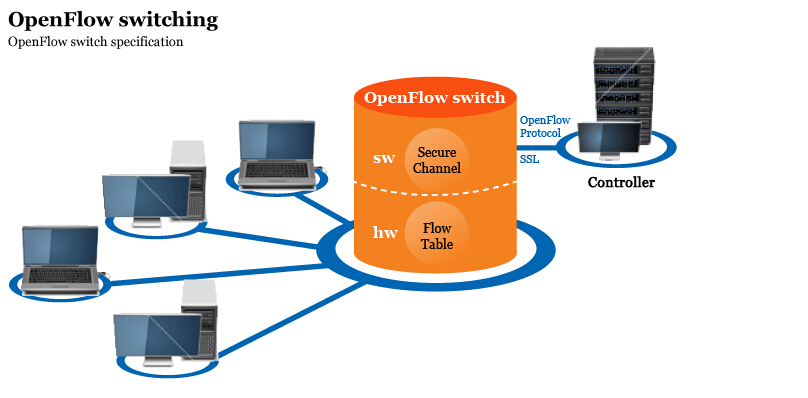
An OpenFlow switch is a software program or hardware device that forwards packets in a software-defined networking (SDN) environment. OpenFlow switches are either based on the OpenFlow protocol or compatible with it.
The OpenFlowSwitch(HWFT, with Hardware Flow Table) reference design provides a set of board-specific projects.
This design achieves a hardware accelerated OpenFlow switch, using multiple stages of FPGA-implemented hardware flow tables, which are cascaded with software flow tables inside the vSwitch running in the CPU.
Demo runs at Linux level.
| Feature | Description |
|---|---|
| Network STD. | IEEE 802.3, IEEE 802.3u, IEEE 802.3ab |
| Physical Layer | 1. 1000/100/10Mbps Copper RJ45 |
| 2. support Auto MDIX, support Auto Neg. | |
| DataLink Layer | 1. RGMII(ONS45 ONS20)/SGMII(ONS30) |
| 2. support Promiscuous Mode (default promiscuous) | |
| 3. support MDIO management to all PHYs | |
| Switch Method | Mixed (Store-and-Forward in software, cut-through in FPGA) |
| Switch Rate | Line rate, FPGA internal BW is 8Gbps |
| OpenFlow | v1.3 |
| Flow Table | Multiple, pipelined, default 64, max 3 impl. by FPGA |
| Meter Table | Supported |
| Match Fields | L2-L4 fields |
| QoS | WRR queuing |
| Metadata | Supported |
| VLAN | Support tag-remove/add/modify |
- For quick start demo.
| File | ONetSwitch30 |
|---|---|
| boot.bin | Download |
| devicetree | Download |
| kernel | Download |
| rootfs (EXT) | Download |
| sw-lib | Download |
| sw-app | Download |
- For image assembling.
| File | ONetSwitch30 |
|---|---|
| system.bit | Download |
| dt source | Download |
| fsbl | Download |
| u-boot (FAT) | Download |
| u-boot (EXT) | Download |
| rootfs (FAT) | Download |
- Additional init./config. script.
| File | ONetSwitch30 |
|---|---|
| script | Download |
- System level
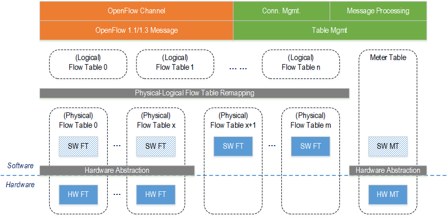
HW FT = Hardware-implemented Flow Table
SW FT = Software-implemented Flow Table
We allow n stages of logical flow tables to be mapped into m stages of physical flow tables, in order to get better flexibility. The physical FTs can be either software-implemented or hardware-implemented.
When implementing HW FTs, the hardware abstraction layer translates the software logic into the values of hardware registers.
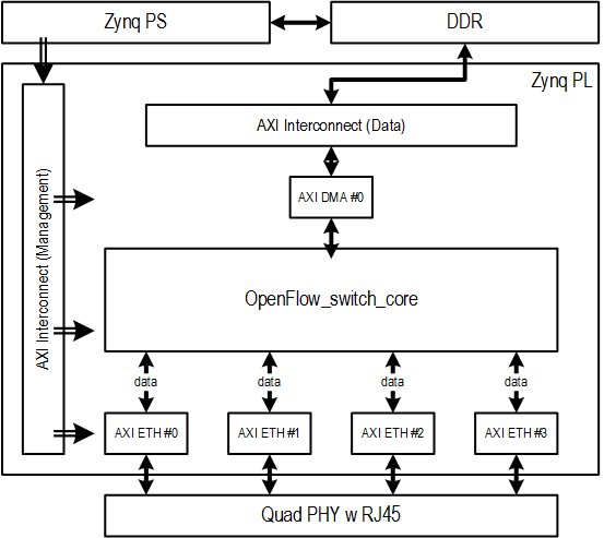
- FPGA Diagram
Notice the difference of priority level between software linked list and hardware TCAM.

Base Address
For Zynq PS address map, please refer to Appx. B of Xilinx UG585.
For MAC and DMA register offset and description, please refer to Xilinx PG138 and Xilinx PG021.
| ONS20/30/45 | BaseAddr | Notes |
|---|---|---|
| axi_dma0 | 0x40400000 | |
| axi_ethernet0 | 0x43c00000 | eth1, MDIO master |
| axi_ethernet1 | 0x43c40000 | eth2 |
| axi_ethernet2 | 0x43c80000 | eth3 |
| axi_ethernet3 | 0x43cc0000 | eth4 |
| packet_pipeline | 0x48000000 | range to 0x48ffffff |
This is a demo without any controller in the scenario. Here’s another page showing how to run with RYU applications.
- Prepare the images in SD/TF card, following the instructions here.
- Setup the topo like below.
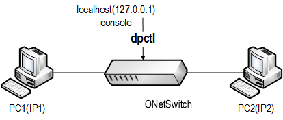
- Without connecting to any controller, manually send entries to enable the bidirectional communication between the two PCs.
*** example ***

zynq> <ofsoftswitch-path>/utilities/dpctl tcp:127.0.0.1:6632 flow-mod cmd=add,table=0,prio=1 in_port=1 apply:output=2
zynq> <ofsoftswitch-path>/utilities/dpctl tcp:127.0.0.1:6632 flow-mod cmd=add,table=0,prio=0 in_port=2 apply:output=1
- Ping each other, should get the response.