↧
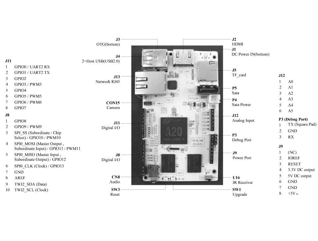
Explanation of headers of pcDuino3 nano
↧
How to use Linker Relay and button to control Desk lamp
In this button, I will demo how to use Linker Relay and button to control Desk Lamp.


First, we need to split the desk temp base

Then take off the two lines connect to the button of the desk lamp, and connect the two lines to Linker Relay
Last, we install the Linker relay and button to the linker Base


The work of the hardware part is done
Then we need to input the code to the Arduino IDE
int relay = 5 ;
int button = 6;

void setup()
{
  pinMode(relay,OUTPUT);
  pinMode(button,INPUT);
}

void loop()
{
  static int LED_Status = 0;
  if(digitalRead(button))
  {
    delay(20);
    if(digitalRead(button))
    {
      LED_Status ++;
      if((LED_Status&0x01))
        digitalWrite(relay,HIGH);
      else
        digitalWrite(relay,LOW);
       delay(200);
    }
  }
}
Power for the pcDuino, and input the code to the Arduino IDE.
Then click the button, and you will see the desk lamp will change light on or off.


↧
↧
Ues Hover on pcDuino board
WHAT IS HOVER?
Hover is a development kit that lets you control your hardware projects in a whole new way. Wave goodbye to physical buttons. Hover detects hand movements in the air for touch-less interaction. It also features five touch-sensitive regions for even more options.
- Prepare
- STEP 1: HOOKUP
- STEP 2: INSTALL THE LIBRARY
- STEP 3: RUN THE EXAMPLE SKETCH
- STEP 4: READING EVENT VALUES
WHAT YOU NEED TO GET STARTED
- pcDuino: You can use any pcDuino board with Hover.
- Hover: The magical board that lets you control your hardware projects with gestures.
- Breadboard: Hover will need to be connected to a breadboard using the 7-pin header.
- Jumper wires: You need 7 of these to connect Hover.
Use the diagram below to connect Hover to your pcDuino board. Here’s a description of all the relevant pins:
- HOST_V+: Connect the HOST_V+ pin to the 3.3V pin on pcDuino.
- RESET and TS: These pins are used by the library to configure Hover. These can be connected to any GPIO pins of pcDuino. Default library uses GPIO 4 for RESET and GPIO 2 for TS.
- SCL and SDA: The I2C pins are used to read data from Hover. Connect SCL/SDA on Hover directly to the SCL0/SDA0 of the pcDuino.
- 3V3 and GND: The 3.3V power supply and ground pins are used to power Hover. Connect these to the 3.3V and GND pins on pcDuino.

With the hardware setup, we’ll need to install the library before we can start hovering. The Hover library lets you easily incorporate gesture and touch events into your projects. We’ve added the library and example code on Github. Hit the link to grab the latest version.
First, run the commands to make sure you have the most updated I2C files:
- sudo apt-get install python-smbus
- sudo apt-get install i2c-tools
Next, plug in your pcDuino and boot it up. Make sure the Hover_example.py and Hover_library.py are in the same folder. Run sudo i2cdetect -y 2 to check if pcDuino can see the Hover on the i2c bus. If you see 42, you’re all set.
Now run sudo python Hover_example.py and you will see ‘Initializing Hover.. please wait’.
Wait a few seconds and you should see a ‘Hover is ready’ message. You can now start waving your hands in the air right above the Hover board in four directions: up, down, left, right. With each swipe of the hand, you should see the corresponding output on the serial monitor window. You can also tap any of the five electrodes (north, south, east, west, and center) and see the output on the serial monitor.

As you may have noticed, each hand wave outputs a specific 8-bit binary value followed by the decoded event type in text (e.g. 00100010 = Swipe Right). The event variable holds the 8-bit binary value to indicate the event type, gesture direction, and tap location.
The upper 3 bits indicates the event type: gesture or tap. The lower 5 bits indicates the gesture direction or tap location. See the image below for all possible combinations of the bit pattern.

These patterns make it easy for you to integrate gestures and taps intro your code. For example, if you only need to detect gestures for your project, consider writing if statements where you check the event variable for the four specific gesture patterns: 01010000, 0100100, 01000100, 01000010.
The original post from http://www.hoverlabs.co/pcduino
↧
Running Aircrack-ng on pcDuino :D – Debian
The original post can be found at: http://pcduino.com/forum/index.php?topic=4943.0
Hay!
Its very cool, my pcDuino is far away from my room, and i can not reach public NETs, and now duino is in front of my hous and i able to run aircrack from SHH.
http://launchpadlibrarian.net/111319328/aircrack-ng_1.1-4_armhf.deb
======================================================
You will need install couple of dependencies, Just read what APT is locking for and install.
One problem was libc6 version >=2.15,
You can do it as follow! IT CAN DAMAGE YOUR SYS.
add this to sources.list
deb http://ftp.us.debian.org/debian/ jessie main contrib
Code:
$apt-get update && apt-get install libc6
remove or comment out from sources.list IMPORTANT !
deb http://ftp.us.debian.org/debian/ jessie main contrib
And after this you will able ti use libc6 >= 2.17
———————————————————————-
Code: [Select]
$airmon-ng start wlan0 mon0
$airodump-ng mon0
CH 8 ][ Elapsed: 8 s ][ 2014-11-08 12:43
BSSID PWR Beacons #Data, #/s CH MB ENC CIPHER AUTH ESSID
02:35:3B:84:12:68 -73 12 0 0 11 54e OPN TELENETHOMESPOT
5C:35:3B:84:12:67 -74 9 0 0 11 54e WPA2 CCMP PSK telenet-41262
5C:35:3B:AA:EC:A8 -78 12 0 0 1 54e WPA2 CCMP PSK telenet-AECA3
02:35:3B:AA:EC:A9 -79 13 0 0 1 54e OPN TELENETHOMESPOT
02:35:3B:AC:DF:3F -83 10 0 0 1 54e OPN TELENETHOMESPOT
5C:35:3B:AC:DF:3E -84 8 0 0 1 54e WPA2 CCMP PSK telenet-CDF39
02:35:3B:A8:A8:35 -83 8 0 0 6 54e OPN TELENETHOMESPOT
5C:35:3B:A8:A8:34 -87 5 0 0 6 54e WPA2 CCMP PSK telenet-8A82F
BSSID STATION PWR Rate Lost Packets Probes
00:1B:11:8D:2C:8C 00:0C:F1:2E:4A:64 -79 5 -11 50 39

 cool stuf. We can put it in the back of car or scooter, whit ACCU for a couple of days. =))))) Imagin
↧
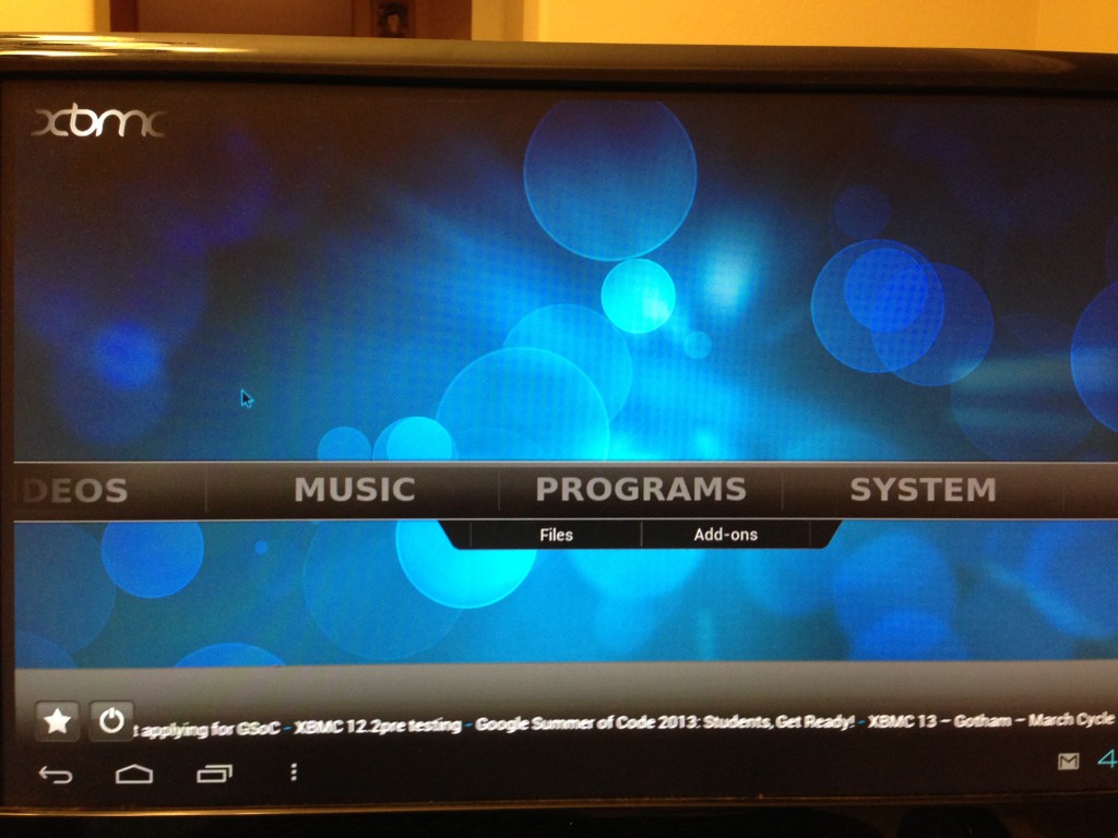
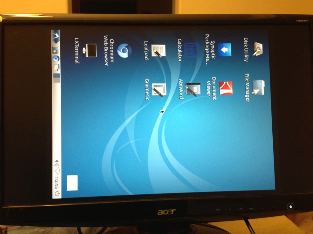
XBMC Android version runs on pcDuino
pcDuino has built-in XBMC for its Lbuntu OS. At the same time, XMBC has android version. We installed it on pcDuino with Android OS. The following is the screen shot.
To install it, we need to flash pcDuino with Android, and download XBMC app at:
http://mirrors.xbmc.org/releases/android/xbmc-12.2-Frodo-armeabi-v7a.apk
↧
↧
Android Release 08142013 version runs on pcDuino1/2
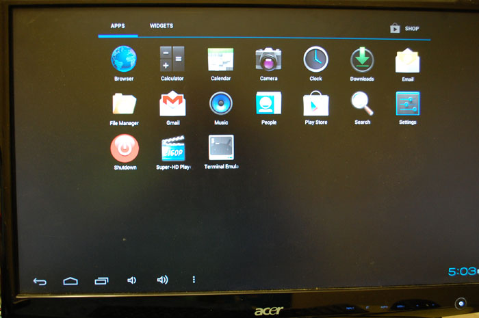
It includes a shutdown APP, and a terminal emulation. It allows Arduino style programming on Android.
↧
Text to Speech (TTS) on pcDuino
In this post, we explains how to install text to speech (TTS) on pcDuino.
First, we need to install the audio control software package:
$sudo apt-get install pulseaudio pavucontrol
For now, we use espeak as TTS:
$sudo apt-get install espeak
Then,we can pass the sentence to espeak:
$espeak "hello, welcome to pcDuinp. I can help you to fullfill your dream." --stdout|paplay

↧
Use Python to read ADC of pcDunio
In this post,we are going to use Linker Slide Potentiometer to show how to use Python to read ADC of pcDuino.
1. We install Linker slide potentiometer on pcDuino. It is connected to [A2 GND, 5V] of pcDuino.
2. Download Python library:
$git clone https://github.com/pcduino/python-pcduino.git
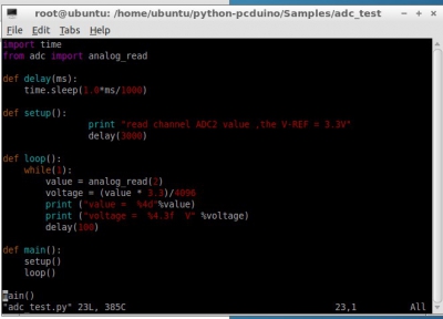
After that, we will see the library files under pcduino. Create a directory named ‘adc_test’ under directory ‘Samples’, the following is the code:
import time
from adc import analog_read

def delay(ms):
    time.sleep(1.0*ms/1000)

def setup():
                print "read channel ADC2 value ,the V-REF = 3.3V"
                delay(3000)

def loop():
    while(1):
        value = analog_read(2)
        voltage = (value * 3.3)/4096
        print ("value =  %4d"%value)
        print ("voltage =  %4.3f  V" %voltage)
        delay(100)

def main():
    setup()
    loop()

main()
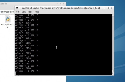
Save, and run:
$python adc_test.py
Adjust the slider, we can see the number changes:
↧
Is It Possible to Rotate Screen in pcDuino?
In this post, we shows how to rotate the screen in pcDuino (Ubuntu OS):
We can add “Rotate” Option in /etc/X11/xorg.conf:
Section "Device"
        Identifier "Mali FBDEV"
        Driver  "mali"
        Driver  "fbdev"   ## This is what changed
        Option  "fbdev"            "/dev/fb0"
        Option  "DRI"             "false"
        Option  "DRI2"             "true"
        Option  "DRI2_PAGE_FLIP"   "true"
        Option  "DRI2_WAIT_VSYNC"  "false"
        Option "Debug" "true"
       Option  "Rotate"    "CW" ## This is what changed
EndSection
Save the change, and reboot pcDuino. We will observe the screen rotated!
↧
↧
Install Transmission BT on pcDuino
Transmission is a BitTorrent client which features a simple interface on top of a cross-platform back-end. Transmission is free software licensed under the terms of the GNU General Public License (GPL), with parts under the MIT License.
In this post, we detailed the steps to install transmission 2.82 on pcDuino. We follow the steps at this page with some modifications.
First, we need to install dependency packages:
$ sudo apt-get install build-essential automake autoconf libtool pkg-config intltool libcurl4-openssl-dev libglib2.0-dev libevent-dev libminiupnpc-dev libminiupnpc5 libappindicator-dev
Then, we can download the source files using:
$wget http://download.transmissionbt.com/files/transmission-2.82.tar.xz
Unzip the tarball:
$tar -xJf transmission-2.82.tar.xz
Now we can start the build:
$cd transmission-2.82
$ ./autogen.sh && make -s
$ make install
Now we need to change the daemon password:
Shutdown:
$sudo /etc/init.d/transmission-daemon stop
Write the rpc-password in the /etc/transmission-daemon/settings.json file, in double-quotes.
Save that file
Startup:
$sudo /etc/init.d/transmission-daemon start
Login to the page, it’s at port 9091
Type in your password.
Please see the following screen shot:

↧
Dual ADC outputs using Linker ADC Shield for Raspberry Pi
In a previous post, we show how to use Linker ADC shield on Raspberry Pi to read ADC value. In this post, we show how to get dual channels from the Linker ADC shield.
We connect two Linker potentiometer modules to the Linker ADC shield as below:
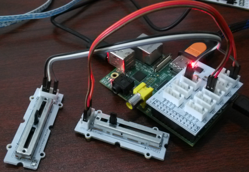
In detail, they are connected in the following way:
- LinkerPotentiometer① – VCC –> Base Shield For RPi VCC
- LinkerPotentiometer① – GND –> Base Shield For RPi GND
- LinkerPotentiometer① – OUT –> Base Shield For RPi (JP1-A0)
-
LinkerPotentiometer② – VCC –> Base Shield For RPi VCC
-
LinkerPotentiometer② – GND –> Base Shield For RPi GND
-
LinkerPotentiometer② – OUT –> Base Shield For RPi (JP1-A1)
The python script is shown below:
import spidev
import time

# A0 = 0, A1 = 1, A2 = 2, A3 =3
adc0 = 0
adc1 = 1

spi = spidev.SpiDev()
spi.open(0,0)

def readadc(adcnum):
# read SPI data from MCP3004 chip, 4 possible adc's (0 thru 3)
    if adcnum > 3 or adcnum < 0:
        return -1
    r = spi.xfer2([1,8+adcnum <<4,0])
    adcout = ((r[1] &3) <<8)+r[2]
    return adcout

while True:
value0 = readadc(adc0)
volts0 = (value0 * 3.3) / 1024
print("ADC%ld = %5.3f V" % (adc0,volts0) )

value1 = readadc(adc1)
volts1 = (value1 * 3.3) / 1024
print("ADC%ld = %5.3f V"% (adc1,volts1) )

print("-------------------------")
time.sleep(0.5)
The results are shown below:
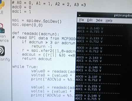
↧
Get Started with Addressable Sealed WS2812 RGB LED Strip
You will be able to control each LED RGB individually with Addressable Sealed WS2812 RGB LED Strip. This opens up a lot of interesting applications, such as the ability to create cool lighting effects for your car, fish tank, or perhaps under cabinet lighting in your kitchen!

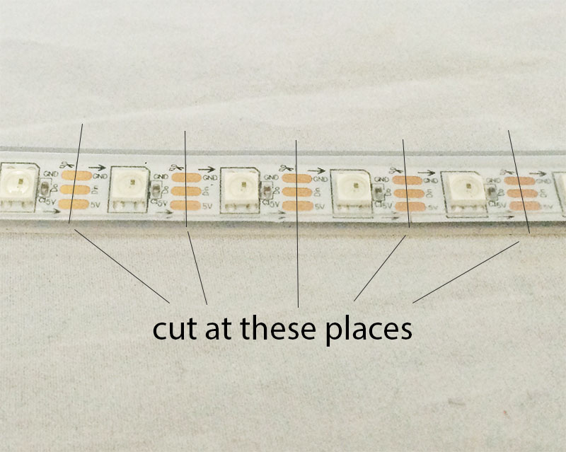
There are two models of the addressable RGB LED strip, 30 LEDs per meter, and 60 LEDs per meter. From the programming point of view, they are same. We just need to provide enough current for the strip. These LED strips can be cut, and connected in serial to form a long strip as long as we provide enough current to power them up.
Features:
- Each LED is individually addressed.
- 24 bit color control
- Controlled by single wire digital communication
- Working voltage: 5V
- Sealed to protect water and it has IP65 rating.
- The length can be cut and glued
Parts List:
In this tutorial, we will use an Arduino Uno to control this addressable RGB LED strip. The required hardware items are below:
- 1 x Arduino Uno
- 1 x USB cable
- Several male to female jumper wires
- LED strip
- Optional: 5V power supply that can deliver large current
Wiring Instruction:
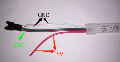
The headers of the LED strip is shown above. The green line is the data communication wire (DAT). The two red wires are for 5V power, and the two white wires are for ground. The extra set of power wires are needed in case extra currents are needed.
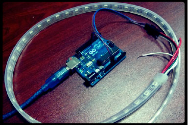
The LED strip is connect to Arduino Uno in the following way:
- DAT of LED Strip –> D6 of Arduino
- 5V of LED Strip –> 5V of Arduino
- GND of LED Strip –> GND of Arduino
Script:
The Arduino script can be downloaded from https://github.com/adafruit/Adafruit_NeoPixel, and unzip to a directory under Arduino IDE.
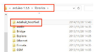
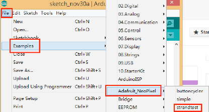
Run the script:
To run the script, launch Arduino IDE and navigate “File -> Examples -> Adafruit_NeoPiexel -> strand test”:
The number 60 in the code needs to be revised to reflect the actual number of LEDs in the whole strip:
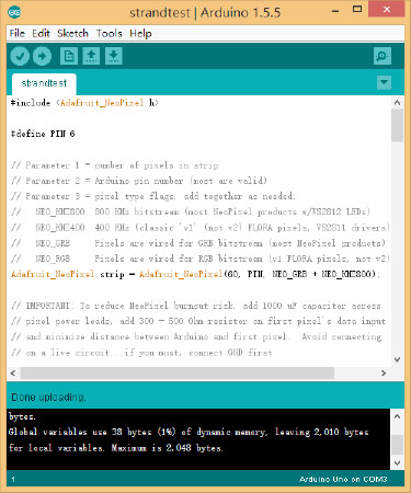
Click ‘upload’ to compile and loaded into Arduino Uno. The final LED show is below:
↧
pcDuino3 with Dell touch monitor S2240T
↧
↧
How to install Flash Player on Android device
Flash is no longer listed under Play Store, however is still possible to download and install it from Archived Flash Player Versions page on the Adobe website.
1. Download the Flash Player apk from the archive page:
Archived Flash Player versions
2. Install the apk
3. Restart your browser
4. Done
Quick links:
Flash Player 11.1 for Android 4.0 (11.1.115.69)
http://download.macromedia.com/pub/f…player_ics.apk
Flash Player 11.1 for Android 2.x and 3.x (11.1.111.64)
http://download.macromedia.com/pub/f…er_pre_ics.apk
↧
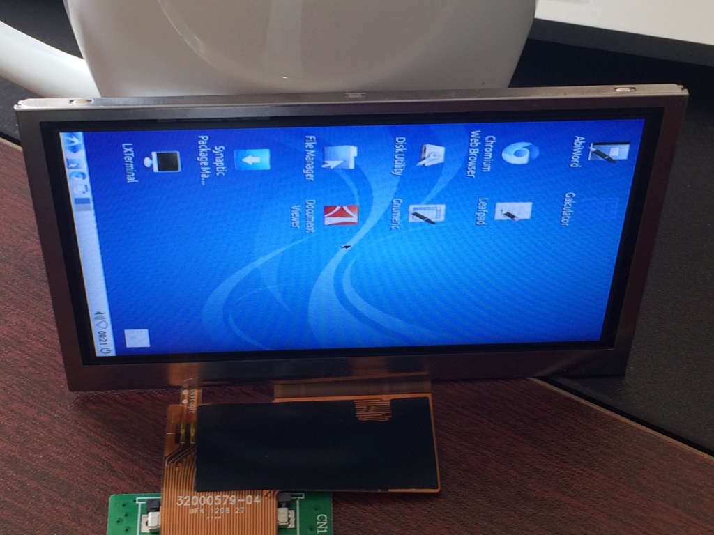
4.3″ LCD for pcDuino3 Nano
The $39 single board computer pcDuino3 Nano is well received after its launch. There are cases that users want LCD of difference form factors. LinkSprite provides a sourcing service and help users port the drivers. In this post, we will show a 4.3″ LCD that we help a customer source.
It’s very difficult to find a 4.3″ LCD as most the LCDs are 7″ for pcDuino3. We are able to find a HDMI to LVDS converter board, and that adapter board itself can be used to connect to a wide range of LCDs of different sizes.
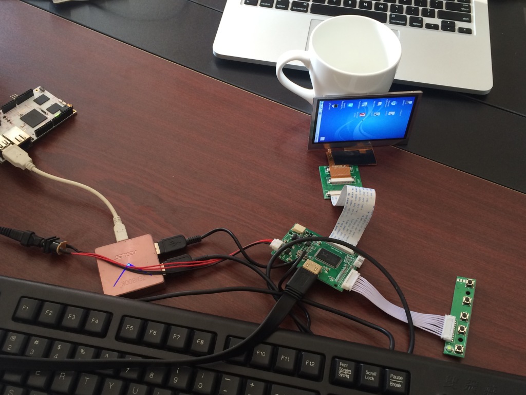
However, this 4.3″ LCD can only support a resolution of 640×350. We can set this resolution by ‘$sudo board-config.sh” command.
Our users also want a portrait configuration. This is possible by following the directions in this post. If it does’t rotate on pcDuino3, we need to comment out the line with ‘Driver mali’.
Here we get:
If you get similar sourcing need, please free feel to contact us at pcduino@linksprite.com!
↧
Cyclon.js support on pcDuino
Alex created a nodejs adapter sot hat cylon can support pcDuino. It’s an on-going project. Right now, it can only support digital pin. The link to the project can be found at:
↧
Install OpenCV on pcDuino and Two Sample Applications
OpenCV is an open source computer vision package based on Python. In this post, we are going to detail the steps to install OpenCV on pcDuino. Two examples are given, one is used to capture an image through the USB camera, the other is to use OpenCV to to face recognition.
Installation Steps:
$ sudo apt-get -y install build-essential cmake cmake-qt-gui pkg-config libpng12-0 libpng12-dev libpng++-dev libpng3 libpnglite-dev zlib1g-dbg zlib1g zlib1g-dev pngtools libtiff4-dev libtiff4 libtiffxx0c2 libtiff-tools

$sudo apt-get -y install libjpeg8 libjpeg8-dev libjpeg8-dbg libjpeg-progs ffmpeg libavcodec-dev libavcodec53 libavformat53 libavformat-dev libgstreamer0.10-0-dbg libgstreamer0.10-0 libgstreamer0.10-dev libxine1-ffmpeg libxine-dev libxine1-bin libunicap2 libunicap2-dev libdc1394-22-dev libdc1394-22 libdc1394-utils swig libv4l-0 libv4l-dev python-numpy libpython2.6 python2.6-dev libgtk2.0-dev pkg-config

$sudo apt-get install libopencv-dev python-opencv

$sudo apt-get install python-dev

$sudo apt-get install libpython2.7 python2.7-dev
$sudo apt-get install python-setuptools python-pip

$sudo ln -s /usr/lib/arm-linux-gnueabihf/libjpeg.so /usr/lib
$sudo ln -s /usr/lib/arm-linux-gnueabihf/libfreetype.so /usr/lib
$sudo ln -s /usr/lib/arm-linux-gnueabihf/libz.so /usr/lib

$sudo easy_install PIL
$sudo pip install -v PIL
If the above comand shows error:
root@ubuntu:/home/ubuntu# sudo pip install -v PIL

Requirement already satisfied (use --upgrade to upgrade): PIL in /usr/local/lib/python2.7/dist-packages/PIL-1.1.7-py2.7-linux-armv7l.egg

Cleaning up...
Change the command to:
$sudo pip install -v PIL --upgrade
Example 1: Capture Image using OpenCV
#!/Users/brent/.virtualenvs/lumber/bin/python

import cv

cv.NamedWindow("w1", cv.CV_WINDOW_AUTOSIZE)
camera_index = 0
capture = cv.CaptureFromCAM(camera_index)

gx = gy = 1
grayscale = blur = canny = False

def repeat():
    global capture #declare as globals since we are assigning to them now
    global camera_index
    global gx, gy, grayscale, canny, blur
    frame = cv.QueryFrame(capture)
    # import pdb; pdb.set_trace()

    if grayscale:
        gray = cv.CreateImage(cv.GetSize(frame), frame.depth, 1)
        cv.CvtColor(frame, gray, cv.CV_RGB2GRAY)
        frame = gray

    if blur:
        g = cv.CreateImage(cv.GetSize(frame), cv.IPL_DEPTH_8U, frame.channels)
        cv.Smooth(frame, g, cv.CV_GAUSSIAN, gx, gy)
        frame = g

    if grayscale and canny:
        c = cv.CreateImage(cv.GetSize(frame), frame.depth, frame.channels)
        cv.Canny(frame, c, 10, 100, 3)
        frame = c
    cv.ShowImage("w1", frame)

    c = cv.WaitKey(10)
    if c==ord('='): #in "n" key is pressed while the popup window is in focus
        gx += 2
        gy += 2
    elif c == ord('-'):
        gx = max(1, gx-2)
        gy = max(1, gy-2)
    elif c == ord('x'):
        gx += 2
    elif c == ord('X'):
        gx = max(1, gx-2)
    elif c == ord('q'):
        exit(0)

    elif c == ord('b'):
        blur = not blur
    elif c == ord('g'):
        grayscale = not grayscale
    elif c == ord('c'):
        canny = not canny

while True:
    repeat()
Sample 2: Face Recognition
Input Image:

Download the above image and save as “opencv_in.jpg”
Output Image:

Test:
#!/usr/bin/env python
#coding=utf-8
import os
from PIL import Image, ImageDraw
import cv

def detect_object(image):
    grayscale = cv.CreateImage((image.width, image.height), 8, 1)
    cv.CvtColor(image, grayscale, cv.CV_BGR2GRAY)

    cascade = cv.Load("/usr/share/opencv/haarcascades/haarcascade_frontalface_alt_tree.xml")
    rect = cv.HaarDetectObjects(grayscale, cascade, cv.CreateMemStorage(), 1.1, 2,
        cv.CV_HAAR_DO_CANNY_PRUNING, (20,20))

    result = []
    for r in rect:
        result.append((r[0][0], r[0][1], r[0][0]+r[0][2], r[0][1]+r[0][3]))

    return result

def process(infile):
    image = cv.LoadImage(infile);
    if image:
        faces = detect_object(image)

    im = Image.open(infile)
    path = os.path.abspath(infile)
    save_path = os.path.splitext(path)[0]+"_face"
    try:
        os.mkdir(save_path)
    except:
        pass
    if faces:
        draw = ImageDraw.Draw(im)
        count = 0
        for f in faces:
            count += 1
            draw.rectangle(f, outline=(255, 0, 0))
            a = im.crop(f)
            file_name = os.path.join(save_path,str(count)+".jpg")
     #       print file_name
            a.save(file_name)

        drow_save_path = os.path.join(save_path,"out.jpg")
        im.save(drow_save_path, "JPEG", quality=80)
    else:
        print "Error: cannot detect faces on %s" % infile

if __name__ == "__main__":
    process("./opencv_in.jpg")
Save the above code to a file named opencv_test.py. After we run it, it will create a directory named opencv_in_face, and save the result pictures in that directory.
↧
↧
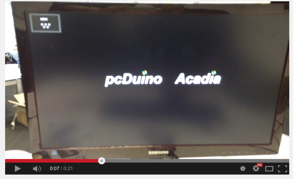
LinkSprite Acadia (i.MX6 Quad Core pcDuino) Booting Process
↧
PCDUINO benchmark review and video playback

Pcduino is like a Raspberry pi only better and faster.
In this video i show the antutu benchmark result for the pcduino
and video playback via youtube.
the pcduino is quite smoth for br
Original video from : https://www.youtube.com/watch?v=bDtHvO5igLA
↧
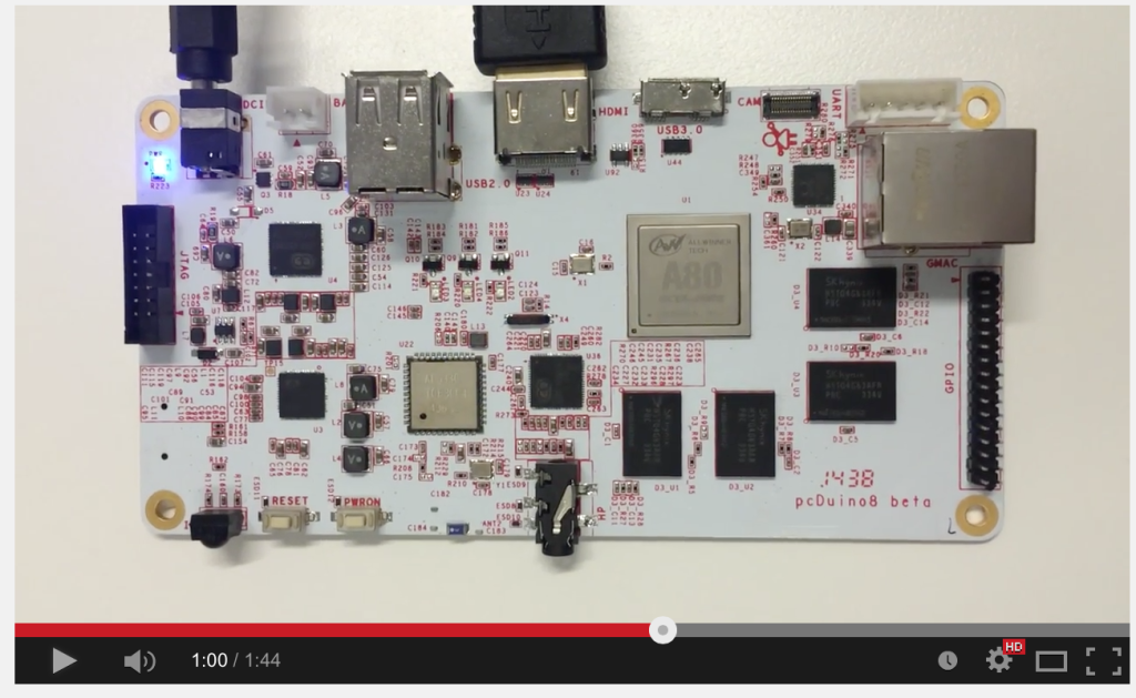
Flash LinkSprite Arches (pcDuino8) with Ubuntu Image
↧