Quantcast
Channel: LinkSprite Learning Center
Viewing all 562 articles
Browse latest View live

Flash Android Image to pcDuino4 STB /pcDuino8 STB

$
0
0

The pcDuino4 STB and pcDuino8 STB are set top box targeting media center applications.

pcduino8_STB_1__82639.1433868506.1280.1280


Since pcDuino4 STB and pcDuino8 STB don’t have SD slots. Many users are asking how to re-flash.   The USB port 0, which is next to the Ethernet RJ45, is the USB OTG port. We will be able to flash image using that USB port using a special USB type  A male to type A male cable.

The flashing process is similar to that in this post. The update button is on the back of the PCBA, and marked as SW2. We should press down SW2 during power cycle for pcDuino4 STB and pcDuino8 STB to enter into OTG flashing mode.


Real Time Kinematic

$
0
0

Real Time Kinematic (RTK) satellite navigation is a technique used to enhance the precision of position data derived from satellite-based positioning systems (global navigation satellite systems, GNSS) such as GPSGLONASSGalileoBeiDou, and GAGAN. It uses measurements of the phase of the signal’s carrier wave, rather than the information content of the signal, and relies on a single reference station or interpolated virtual station to provide real-time corrections, providing up to centimetre-level accuracy. With reference to GPS in particular, the system is commonly referred to as Carrier-Phase Enhancement, or CPGPS.[citation needed] It has application in land survey and in hydrographic survey.


The full wiki can be found at: https://en.wikipedia.org/?title=Real_Time_Kinematic

USB Serial Device for Android

$
0
0

USB Serial Dvice for Android

Posted By: Vinayakhegde

Original discussion can be seen here.

Root the pcDuino3 by installing SuperSU from the google play store.

Install ES File Explorer

Install the Terminal Emulator if it is not already.

Open terminal window and become a super user by executing “su” command.

Remount file system as writable by executing “busybox mount -o remount,rw /system”

Use ES File Explorer to create “android.hardware.usb.host.xml” into folder “/system/etc/permissions”. Edit the new file so that it contains the following…

<?xml version="1.0" encoding="utf-8"?>
<permissions>
<feature name="android.hardware.usb.host"/>
</permissions>

Edit file “handheld_core_hardware.xml” or “tablet_core_hardware.xml” in the same folder as above to include the line, “<feature name=”android.hardware.usb.host” />” inside  the permissions area denoted by “<permissions>” and “</permissions>”.

Reboot


You should now see your USB serial device when connected.e

Use Cross Compiler to Build Application for pcDuino3

$
0
0

We will need to use cross compiler to build the application on X86 machine, in cases that the application is big enough that the building process on pcDuino3 itself will take too much time.


To do the cross compilation for a pcDuino3 with Lbuntu 12, we must do that on a X86 PC with Ubuntu 12.04. It can be either 32 bit or 64 bit. But it must be Ubuntu 12.04. The toolchain that we are going to use is arm-linux-gnueabihf-gcc /g++ 4.6.3.


1. Install gcc cross compile tool on Ubuntu12.04

 $sudo apt-get install gcc-arm-linux-gnueabihf


2. Install g++ cross compile toolchain on Ubuntu12.04

 $sudo apt-get install g++-arm-linux-gnueabihf


3. Cross compile:

Open a file by ryping ‘$vi helloword.c’.

Enter the following code:

#include <stdio.h>

int main(void)

{

        printf("Hello World!\n");

}


4. Build the code:

$arm-linux-gnueabihf-gcc helloword.c -o helloword

Now we can copy helloword to pcDuino3 and execute it there.

Create a SD card using Win32DiskImager for LinkSprite Acadia

$
0
0

In this post, we highlight the steps used to create a  SD card using Win32DiskImager for LinkSprite Acadia.

The image can be downloaded from the image page.

Windows:

Launch win32diskimager and plug in a SD card (please use a SD USB adapter, SD card should have a capacity larger than 4GB):

acadia_image_1

Note: please use the image with a version with v1.2 or above.

Click ‘Write':

acadia_image_2


?

1
$dd if=./acadia_ubuntu12.04_v1.0_tf.img of=/dev/rdisk3 bs=1M


The TF card will be mounted as dev/rdisk3. Use the command ‘$unmount /dev/disk3s1′ to unmount, and create a SD card using:

After its done, it will prompt:

acadia_image_3


Install it in the SD card slot 1, and turn on power, Acadia will boot.

Basic knowledge points of BLE Module

$
0
0

bluetooth


1. What is BLE?

Starting from Bluetooth 4.0, there are two branches: classical 4.0 and BLE 4.0.  The classical 4.0 is the upgraded version of Bluetooth 3.0 and is compatible with the previous lower versions. But BLE 4.0 is a brand new branch, and is NOT compatible with the previous versions. BLE is bluetooth low energy, i.e., it has very low power consumption.


2.  What kinds of devices support BLE?

iPhone4s, 5, 5c, 5s, iPad 3,4, mini support BLE, and don’t need MFI certification.  For Android devices, only Android smartphone with Bluetooth 4.0 hardware and Android 4.3 and above.

3. Why is BLE not supported on PC?

If a Bluetooth 4.0 dual mode (dual mode refers to classical 4.0 and BLE 4.0) adaptor is installed on the PC,  the adaptor supports BLE hardware-wise. However, the dilemma right now is that we cannot find the proper driver.

4. Why we cannot find the BLE device in the Bluetooth icon under the smartphones system menu?


The Bluetooth of the smartphone is default to work under classical mode. We need to use the proper APP to search, pair, connection and communication.  For iOS, please use LightBlue, and use BLE serial port under Android.

Get Started with Freescale Freedom Board with mbed

$
0
0

At FTF 2015, we attended an mbed workshop. It amazed us so much that its so easy to use. In this tutorial, we show how to use Freescale Freedom board with mbed.


To use the Freedom board, first we plug it to the USB port of a Windows PC using the microUSB port marked as OpenSDA.

IMG_0032[1]


For the first time, Windows will install proper driver, and the freedom board will show up as a USB driver.

IMG_0033[1]


Open the html page that resides on the USB driver:


IMG_0034[1]


It will asks for your mbed developer username and password. Create one if you don’t have one.

IMG_0035[1]


After we log in, we will see that the freedom board will linked to our account.

IMG_0036[1]


Scoll down the page, and we will found a sample application, “helloworld”:

IMG_0037[1]


Click “Import programa” and the browser will open  new tab showing the code files and complier. Click ‘Compile all’, it will build the code and prompt to download the binary file:

IMG_0040


After download, copy the binary to the USB driver that created by the freedom board. The board will flash its memory using the file dragged to it, and the program will work after we hit the reset button.


Get started with Nordic nRF51-DK with mbed

$
0
0


The nRF51 Development Kit is a single-board development kit for Bluetooth Smart, ANT and 2.4GHz proprietary applications using the nRF51 Series SoC. This kit supports both development for both nRF51822 and nRF51422 SoCs.


The USB port supports both J-Link and mbed toolchains. In this post, we show the details on how to using the mbed programming environment  to develop BLE 4.0 application.


nRF51-DK defaults with J-Link. So the first step is to flash it with mbed CMSIS-DAP software. To load it, press the RESET button:
IMG_0346


While the RESET button is pressed, connect it to the USB port of the PC with the power switch to ON position.


IMG_0347


nRF51-DK  will show up as a USB drive labeled as ‘BOOTLOADER':

IMG_0348


Go the the nRF51-DK website to download the firmware needed for mbed. Scroll down to the firmware section and download it:

IMG_0350


IMG_0351


Drag the downloaded bin file to the USB drive that labeled as ‘BOOTLOADER’.  The boar will start to flash its memory automatically, and after its done. the USB drive will unmount, and the LED will blink constantly.

IMG_0353


Power cycle the board, the nRF51-DK will show up as a USB drive again, but will a label ‘MBED':

IMG_0354


Go to the nRF51-DK website again, and find the mbed compiler,

IMG_0356


Import the sample projects:

IMG_0357


IMG_0358


And find the BLE heart rate:

IMG_0359


IMG_0360


And then click the compile button,

IMG_0361


IMG_0362


After the build process is finished, it will prompt to save the output hex file:

IMG_0363


IMG_0365


Drag the hex file to the USB drive labeled as ‘mbed’. Power cycle the board.

On the APP side, take an iOS device, and install two apps, ‘lightblue’ and ‘nRF Utility’.

IMG_0044


Use lightblue to check the nearby BLE device, and we find a device named ‘HRM1′. This is the board itself.

IMG_0045


Now we can use nRF Utility to talk to the board.
IMG_0046 IMG_0048 IMG_0049 IMG_0050 IMG_0051


Acadia 3.0 root filesystem to HDD

$
0
0

This is not an elegant solution but it does work.

When I created the bootable SD card I made another on a USB thumb drive. I connect my SATA hard drive to the Acadia, insert the bootable SD and boot up. Once booted insert the thumb drive. Next I use dd to copy thumb drive contents to the hdd. Use Gparted to resize hdd partition to fill the empty space. Once these things are done then we are ready to get our hands dirty by editing uboot environment variables.

I connected a FTDI cable to the debug port of the Acadia. Settings are 115200,N,8,1. Reboot Acadia and you should see u-boot pause for a few seconds. Press any key to stop the boot process and enter u-boot command line.

At the u-boot prompt enter:

u-boot>setenv bootarg_mmc 'setenv bootargs ${bootargs} root=/dev/sda1 rootwait fec_mac=${ethaddr} video=mxcfb0:dev=hdmi,19200x1080M@60,if=RGB24,bpp=32 fbmem=28M'

u-boot>saveenv

Upon reboot the Acadia will start the boot process from the SD card but the filesystem on the hard drive will be mounted as root.


If anyone needs further information I can break this down into smaller steps.

Android build instructions for A20 based pcDuino3 family

$
0
0

The Android source files for pcDuino3 family has been released in the image download page.

The following are the steps to build the Android OS for pcDuino3:

1) Kernel

#cd lichee
#./build.sh -p sun7i_android

2) Android

#cd ../android
#. build/envsetup.sh
#lunch wing_pcduino-eng
#extract-bsp
#make -j16
#make
#pack

There are many differences between different options:

  • Display (HDMI/LVDS)
  • Audio Output (HDMI/Headphone)
  • Ethernet(100M/1000M)
  • Wifi(RTL8188EUS/RT5370)

To build Android for different option, the description is as follows:
1. The display  defaults with HDMI version, and if you need to make the display as LVDS. Please do the following to change:

Before build the kernel:

#cd lichee/tools/pack/chips/sun7i/configs/android/wing-pcduino/?

Use sys_config_lvds.fex to replace sys_config.fex

2. Audio defaults with HDMI output, and if you want to make the microphone jack output. Please modify the file android/device/softwinner/common/hardware/audio/audio_hw.c
Change
#define CARD_A1X_DEFAULT CARD_A1X_HDMI
to
#define CARD_A1X_DEFAULT CARD_A1X_CODEC

3. The Ethernet defaults with 1000M. If you want to change it to 100M. Please modify lichee/linux-3.4/arch/arm/configs/sun7ismp_android_defconfig
Change
CONFIG_SUNXI_GMAC=y
CONFIG_GMAC_SCRIPT_SYS=y
CONFIG_GMAC_CLK_SYS=y
CONFIG_GMAC_RING=y
# CONFIG_GMAC_CHAINED is not set
# CONFIG_SUNXI_EMAC is not set

to
# CONFIG_SUNXI_GMAC is not set
CONFIG_SUNXI_EMAC=y

4. The WiFi defaults with RTL8188EUS. If you need to change it to RT5370 Wifi dongle, please modify
1) lichee/bootimg/boot.ext4
rm boot.ext4
ln -s boot_rt5370.ext4 boot.ext4

2) android/device/softwinner/wing-pcduino/BoardConfig.mk
Change
BOARD_WIFI_VENDOR := realtek
#BOARD_WIFI_VENDOR := ralink
to
#BOARD_WIFI_VENDOR := realtek
BOARD_WIFI_VENDOR := ralink

How to use python-serial on pcDuino

$
0
0

When using python, some people may meet the situation that serial ports( GPIO0 and GPIO1) cannot send or receive data on pcduino, but without any problem on Arduino. And when back to python, the connection under python-serial is normal too. This is because the gpio0 and gpio1 on python didn’t set to UART mode. Now we are going to set UART mode on python. When setting mode on pcduino GPIO, we could use code to the folder below, generally, “0” for input mode, “1” for output mode. “3” can be used to set UART:

/sys/devices/virtual/misc/gpio/mode/

Install python-serial:

sudo apt-get instal python-serial

test code:

import serial 

with open("/sys/devices/virtual/misc/gpio/mode/gpio0",'w') as UART_RX: 
    UART_RX.write('3') 

with open("/sys/devices/virtual/misc/gpio/mode/gpio1",'w') as UART_TX: 
    UART_TX.write('3') 

myport = serial.Serial("/dev/ttyS1",9600,timeout=10) 
myport.open() 

myport.write('python serial  test on pcduino\n') 

data = myport.readline() 
if len(data)&gt;0: 
     print(data) 

myport.close()

Save the test code above as “serial_test.py”, then run:   sudo python ./serial_test.py ( circumscribe a USB to serial port module and pcduino serial port in order to connecting, or, use jumper to short connect RXD and TXD, and the terminal will print the data ” python serial test on pcduino”) :

1

use the serial debugging tools from PC send data to pcduino:

2


How to use BLE4.0 Shield

$
0
0

Bluetooth4.0

BLE4.0 Shield is an arduino shield which based on TICC2541. The AT instruction set integrated by BLE4.0 module is simple and effective to use, and greatly shorten your developing period. Based on the bluetooth standard specification, Bluetooth Low Energy (BLE) technology allows BLE4.0 to further reduce peak power to half, comparing with traditional Bluetooth devices. The single-mode chip of Blue tooth4.0 (BLE) enables to work for a long time (up to several months even years), powered by single button battery. Instead, traditional Bluetooth technology generally asks for at least two AA batteries, meanwhile at most works for several days or weeks. The main disadvantage of previous blue tooth version is extremely low startup speed. For example, Blue tooth 2.1 spends 4s to startup, but it’s only takes 3 ms for Blue tooth 4.0 to startup. If comparing Blue tooth 2.1 to a basic “feature phone”, then, Blue tooth 4.0 would be a “smart phone”.

Arduino UNO x1

BLE4.0 Shield x1

mobile device with Blue tooth 4.0 x1

#include <SoftwareSerial.h> 

#define RxD 2
#define TxD 3
SoftwareSerial mySerial(RxD,TxD); 

void setup() 
{ 
    pinMode(RxD, INPUT); 
    pinMode(TxD, OUTPUT); 
    mySerial.begin(9600);               // the ble4.0 baud rate  
    Serial.begin(9600);                 // the terminal baud rate   
} 

void loop() 
{ 
    if(Serial.available()) 
    { 
       mySerial.print((char)Serial.read()); 
    }  

    if(mySerial.available()) 
    { 
       Serial.print((char)mySerial.read()); 
    }   
}

(1) plug 0 shield in ArduinoUNO, and use a jumper cap to short circuit ( D2-BT_TX, D3-BT_RX), open ArduinoIDE and download test code:

图片2

untitled


(2) open serial debugging window at right side of Arduino(baud rate 9600), send “AT” (attention: AT on this module should not add carriage return), we can see the module back to “OK”, then set the module to subordinate module:

check client-server mode: AT+ROLE? back: OK+GET:0 (“0″ represent server mode, “1” represent client mode)

modify to server mode”AT+ROLE0″ back: OK+Set:0

check module name: AT+ROLE? back: OK+NAME:BLE_Shield

edit module name: AT+NAMExxx back: OK+Set:xxx

(3) install “lightblue” on mobile device, open software and search for Bluetooth devices, then connect to device named “BLE_Shield” and transfer data:


untitled

*click “listen for notifications” button monitor ( turn to “stop listening” after click it), receive data. Meanwhile, send test type string at ARduinoIDE serial port, and the data can be received:

untitled

untitled

*click ” Write new value”, send test type strings, and then you can receive type strings at ArduinoIDE sent by mobile device:

untitled

untitled

LED D1 :

When bluetooth ready to connection, LED blicking; when module have been connected device, LED continue bright.

press S1 ( for about 1s):

(1) module remains in sleeping mode:

module will return to normal mode, if open AT+NOTI, serial port will receive OK+WAKE

(2) module remains in connect mode:

module will initiate the request to disconnect

(3) module remains in standby mode:

module will restore to factory default setting.

SWITCH:

choose the GPIO level of micro-controller which connects with BLE4.0 is 3.3v or 5v.

DIY Smart Home based on pcDuino and BLE4.0

$
0
0

untitled

Before this article, there is post about DIY Smart home connecting through Wifi. Nowadays, the wearable devices such as smartbands and smart watch are extremely popular. So it’s time to talk about Bluetooth4.0, this article is all about how to DIY your own smart home using BLE4.0 Shield and BLE4.0 Bee as connection devices, pcduino as openhab server, Arduino as device.

Install software about openhab on pcDuino, get more detail form linksprite learn center:

http://learn.linksprite.com/?s=openhab

or, download the image file below, then update ( install openh under “/opt/openhab” folder):

http://pan.baidu.com/s/1ntHtCyX?qq-pf-to=pcqq.c2c code: fh6c

For more detail about how to  use BLE4.0 shield ( the usage of BLE4.0 Bee is the same as BLE4.0 Shield )

http://cnlearn.linksprite.com/?p=7879#.VZpKvfmqqko

(1) test code of python-mqtt:

import socket 
import sys 
import paho.mqtt.publish as publish 
import paho.mqtt.client as mqtt 

import serial 
myport=serial.Serial('/dev/ttyS1',9600,timeout=1) 

myport.write('test') 

###  

client_connect=0

## 
def on_connect(mqttc, obj, flags, rc): 
    print("rc: "+str(rc)) 
def on_message(mqttc, obj, msg): 
    if client_connect==1: 
       myport.write('S') 
       print(msg.topic+" "+str(msg.qos)+" "+str(msg.payload)) 
       connection.send(msg.topic+" "+str(msg.payload)) 
def on_publish(mqttc, obj, mid): 
    print("mid: "+str(mid)) 
def on_subscribe(mqttc, obj, mid, granted_qos): 
    print("Subscribed: "+str(mid)+" "+str(granted_qos)) 
def on_log(mqttc, obj, level, string): 
    print(string) 

#### The following for TCP/IP from Arduino-style part ############# 
# Create a TCP/IP socket 
sock = socket.socket(socket.AF_INET, socket.SOCK_STREAM) 
sock.setsockopt( socket.SOL_SOCKET, socket.SO_REUSEADDR, 1) 

# Bind the socket to the port 
#server_address = ('localhost', 10000) 
server_address = ("192.168.1.134", 10000) 
print >>sys.stderr, 'starting up on %s port %s' % server_address 

sock.bind(server_address) 

# Listen for incoming connections 
sock.listen(1) 

################ The following for subscribing to MQTT ############## 
mqttc = mqtt.Client() 
mqttc.on_message = on_message 
mqttc.on_connect = on_connect 
mqttc.on_publish = on_publish 
mqttc.on_subscribe = on_subscribe 

mqttc.connect("localhost", 1883, 60) 

### Subscribe to topic '4033', which is the ID of the relay of garage 
mqttc.subscribe("4033", 0) 
mqttc.loop_start() 

while True: 

    # Wait for a connection 
    print >>sys.stderr, 'waiting for a connection'
    connection, client_address = sock.accept() 
    client_connect=1

    try: 
       print >>sys.stderr, 'connection from', client_address 

       # Receive the data in small chunks and retransmit it 
       while True: 
       # debug   
           #connection.send('Hello world') 
           ble_data = myport.readline() 
           if len(ble_data)>0: 
              print(ble_data)   
           #data = connection.recv(3) 
           #print(data) 
           #if len(data)==0: 
             #connection.close() 
             #break

           if "test" in ble_data : 
               print('okay') 

           if "321" in ble_data: 
               print >>sys.stderr, 'publish 0'
               publish.single("3032", "0",hostname="localhost") 
           if "123" in ble_data: 
               print >>sys.stderr, 'publish 1'
               publish.single("3032", "1",hostname="localhost") 

    except KeyboardInterrupt: 
       # Clean up the connection 
       connection.close() 
       sys.exit(1)

(2) test code of Socket:

#include "core.h"
#include "stdio.h"
#include "stdlib.h"
#include "string.h"
#include <sys/socket.h> 
#include <netinet/in.h> 
#include <arpa/inet.h> 

int sockfd,n, flags; 
socklen_t addr_len; 
struct sockaddr_in servaddr,cliaddr; 
char sendline[1000]; 
char recvline[1000]; 
int rc; 

void setup()  
{ 
  sockfd=socket(AF_INET,SOCK_STREAM,0); 
  bzero(&servaddr,sizeof(servaddr)); 
  servaddr.sin_family = AF_INET; 
  servaddr.sin_addr.s_addr=inet_addr("192.168.1.134"); 
  servaddr.sin_port=htons(10000); 
   Serial.begin(9600); 
  if((rc = connect(sockfd, (struct sockaddr *)&servaddr, sizeof(servaddr)))<0) 
    { 
      perror("Client-connect () error"); 
      exit(-1); 
    } 

  flags=fcntl(sockfd,F_GETFL); 
  flags|=O_NONBLOCK; 
  fcntl(sockfd,F_SETFL,flags);   
} 
void loop()  
{ 

}

(3) test code of Arduino

#include <SoftwareSerial.h> 

#define RxD 11
#define TxD 12
SoftwareSerial mySerial(RxD,TxD); 

char dat; 
int i,flag=1;  
void setup() 
{ 
    pinMode(RxD, INPUT); 
    pinMode(TxD, OUTPUT); 
    pinMode(13,OUTPUT); 
    pinMode(8,INPUT);  
    digitalWrite(8,HIGH); 
    mySerial.begin(9600);               // the ble4.0 baud rate  
    Serial.begin(9600);                 // the terminal baud rate   
} 

void loop() 
{ 
    if(Serial.available()) 
    { 
       mySerial.print((char)Serial.read()); 
    }  

    if(mySerial.available()) 
    { 
       dat = char(mySerial.read()); 
       Serial.print(dat); 
       if(dat == 'S') i++; 
       if(i%2) digitalWrite(13,LOW); 
       else digitalWrite(13,HIGH); 
    }   

    if( (digitalRead(8)==1)&&(flag==1))  
    { 
      flag = 0 ; 
      mySerial.write("123\r\n"); 
      Serial.write("123\r\n"); 
    } 
    if( (digitalRead(8)==0)&&(flag==0)) 
    {  
      flag =1 ; 
      mySerial.write("321\r\n"); 
      Serial.write("321\r\n"); 
    } 
}

pcduino3 x1

ArduinoUNO x1

BLE4.0 Bee x1

BLE4.0 Shield x1

Xbee Shield x1

Door Sensor x1

Linker LED x1

pcDuino3 x1

(1) install openhab on pcDuino and APP on mobile device:

untitled

(2) build a file “mqtt-BLE.py”, copy the code of python-mqtt in it, remember to edit IP address to the IP address that read now:

*edit IP address based on distribution by pcDuino ( check by $ifconfig ), following is the location:

untitled

(3) open “/home/ubuntu/c_environment/sample”, add a c file, copy the test code in it (need to add socket in Makefile of current directory, besides, edit IP address into ( the same as (2) ) ;

untitled

(4) weld two lines of entrance guard sensor to D8 and GND of Arduino ( set D8 as pull-up input, when the magnet of entrance guard sensor approached, the IO level will drop ) , then connect linker LED with D13 and GND, BLE4.0  on Arduino, and then download the test code of Arduino ( both switches of Xbee Shield should on the left side) :

untitled

untitled

(5) turn on pcDuino, run openhab, python MQTT, socket:

#turn on openhab:

$cd/opt/openhab

$sudo ./start.sh

(if openhab mirror image has been build, add a self-start in it : sudo /opt/openhab/start.sh )

#run MQTT :

$cd/ home/ ubutu

$sudo python ./mqtt_publish.py

untitled

#run socket ( this program should be run after python mqtt ):

$cd /home/ubuntu/c_enviroment/sample

$sudo ./socket

(6)  the socket connection was build, after the program above start up:

untitled

(7) Now we can open the APP of mobile device, click settings, edit setting below :

untitled


Edit IP address based on pcDuino, set up user name and code as following:

$cd /opt/openhab/configurations

$vim ./users.cfg

“test” is user name, “12345678” is code.

untitled

(8) after setting, click “save” at right side, then it will be return to the main interface ( click button can control light) :

#when door is open, LED turn off :

untitled

untitled

#when door is close, LED will open :

untitled

untitled

How to use Nixie tube module on Arduino

$
0
0

NIXIE-module-Q30-1 module is designed to work with nixie tube QS30-1/SZ-8. Combined with classic nixie tube, ceramic tube socket, gold plated PCB, RGB background LED, QS30 module can be used for a variety of applications, to fulfill your requirements to display numbers with colorful effects. It is a compact design in a minimal footprint, packed with voltage boost circuit, display driver and user-friendly tube sockets. Multiple modules can be daisy chained in sequence for more imaginative needs.

This nixie tube module extends the power of Arduino, allowing users to easily integrate nixie tubes into their own Arduino projects, or any projects using similar open source platforms. Users can focus on implementing their ideas with no need to worry about the power management or display driving.

nixietube_2

Features:

  • Vintage nixie tube, model QS30-1/SZ-8/SW3-1 (made in Chinain 1961-1989)
  • Open source library for Arduino
  • Hassle-free voltage boost circuit integrated.
  • Easily expandable
  • Gold-plated PCB
  • Ceramic tube socket
  • RGB LED backlighting

Pin Assignment:

Pin Symbol Description
1 5V DC 5V DC power in
2 GND Ground
3 DIN (Pin side) /DOUT (Socket side) Serial data input (Pin side)/Serial data output (Socket side)
4 OE Output enable (active LOW), brightness control
5 STCP Storage register clock input
6 SHCP Shift register clock input
  1. 1 x Arduino Uno
  2. 1 x Nixie Tube Module V2.0
  3. 6 x Female to male jumper wires

We connect the tube module to Arduino Uno in the following way:

  1. Nixie Tube Module SHCP   ->  Arduino D13
  2. Nixie Tube Module STCP   ->  Arduino D12
  3. Nixie Tube Module OE      ->  Arduino D10
  4. Nixie Tube Module DIN     ->  Arduino D11
  5. Nixie Tube Module GND    ->  Arduino GND
  6. Nixie Tube Module DC5V  ->  Arduino 5v

#include ”NixieTube.h”

#define COUNT 1

// define how many modules in serial

NixieTube tube(11, 12, 13, 10, COUNT);

// pin_ds, pin_st. pin_sh, pin_oe(pwm pin is preferred), COUNT

void setup()

{

  tube.setBackgroundColor(0, (Color)5);

  // set different background color for each module

  tube.setBrightness(0xff);

  // brightness control, 0×00(off)-0xff

  tube.display();

}

void loop()

{

  for(int i;i<7;i++)

  {

    tube.setNumber(0,i);

    tube.setBackgroundColor(0, (Color)i);

    tube.display();

    delay(500);

  }

}

1. Picture of the setup:

2. Download the Arduino library to under ‘arduino-1.0/libraries':

3. Launch Arduino IDE, copy and paste the test code, and download to Arduino Uno:

4. Running effect:

In a chain,

We can download the libraries and datasheet here:

1. Arduino library: NixieTubev2
2. User manual:NIXIE Module QS30-1 Manual EN v2.0.0

Use the Nordic nRF51-DK to program Openhapp Bluetooth 4.0 BLE Sensor Tag/iBeacon Station NRF51822 with mbed

$
0
0

Openhapp has a bluetooth 4.0 BLE sensors tag with iBeacon station function that is powered by NRF51822. On the board, the following sensors are integrated:

  • 3-axis accelerometer MPU6050
  • Bosch temperature and pressure sensor BMP180
  • Ambient light sensor AP3216
  • Power switch

It will be nice if we can use mbed to program the openhapp Bluetooth sensor tag. In this post, we show how to use Nordic nRF51-DK as a mbed programmer to program the openhapp Bluetooth sensor tag.


If we look at the schematic of nRF51-DK, we can find the headers for programming external board:

nrf51_1


The physical location of this header can be found on nRF51-DK as below:

nrf51_2


Wire out the 4-wire debug of openhapp bluetooth sensors tag. We can cut one side of the 0.1″ female to female jumper wires, and solder them to the debug points:

nrf51_3


nrf51_4


Wire instructions (we connect the debug port of the openhapp sensors tag to the programmer headers of nRF51-DK):

  • nRF51DK- SH_SWCLK –>   sensors tag – CLK
  • nRF51DK – SH_SWDIO   –>sensors tag – DIO
  • nRF51DK- SH_VTG       –>sensors tag – VCC
  • nRF51DK – SH_GND       –>sensors tag -GND

nrf51_5


When we program the sensors node, the sensors node needs to be powered externally by a button cell. We install the CR2032 battery on the back of the sensors node, and turn on the power switch of the sensor node:

nrf51_6


nrf51_7


We will blink the LED on the sensors node. First we look at the schematic of the sensor node and found that LED are connected to P0_17/18/19 of the NRF51:

nrf51_8


Open mbed web IDE environment, and enter the following code:

#include "mbed.h"

DigitalOut myled(P0_18);

int main() 
{
    while(1)
    {
        myled = 0;
        wait(0.5);
        myled = 1;
        wait(0.5); 
    }
}

Note: When we select the target board, it should NOT be Nordic nRF51-DK, and we should select Nordic nRF51822 (Click the upper right corner of the IDE to select):

nrf51_9


Click the button to build the code, and we will get a hex file:

nrf51_10


nrf51_11

Drag and place it into the USB drive that starts with mbed to flash this hex file to the sensor tag. The LED on the sensor tag will start blinking:

nrf51_12


IoT home automation with openHAB on pcDuino3B

Create bootable SD card for pcDuino8 Uno

Using the pcDuino with the Joey Hurdy 3x3x3 LED Cube – Experiment

$
0
0

http://kurtroesener.blogspot.com/2015/09/using-pcduino-with-joey-hurdy-3x3x3-led.html

Acadia: How to expand to the full space of SD card

$
0
0

Acadia v3 uses a SD card to boot. After we load the bootable SD card, if we want to use the full space of the SD card, we should run the following command:

$resize2fs /dev/mmcblk0p1

pcDuino8 Uno install of ROS Indigo

$
0
0

ROS Indigo Igloo will be primarily targeted at the Ubuntu 14.04 LTS (Trusty) release, though other Linux systems as well as Mac OS X, Android, and Windows are supported to varying degrees. For more information on compatibility on other platforms, please see REP 3: Target Platforms.

Indigo supports releasing, documenting and integration testing of catkin-based packages only. This is especially driven by the goal to provide long term support of this distribution. Building rosbuild-based packages from source is still supported though.

1. Installation

1.1 Set your Locale

Boost and some of the ROS tools require that the system locale be set. You can set it with:

sudo update-locale LANG=C LANGUAGE=C LC_ALL=C LC_MESSAGES=POSIX

1.2 Setup the sources.list

Setup your computer to accept software from the ARM mirror on packages.ros.org.

Due to limited resources, there are only active builds for Trusty armhf (14.04), since this is the stable, long-term Ubuntu release and is the most-requested distribution in conjunction with ROS Indigo.

Ubuntu 14.04 (Trusty armhf)

sudo sh -c 'echo "deb http://packages.ros.org/ros/ubuntu trusty main" > /etc/apt/sources.list.d/ros-latest.list'

1.3 Set up your keys

wget https://raw.githubusercontent.com/ros/rosdistro/master/ros.key -O - | sudo apt-key add -

1.4 Installation

First, make sure your Debian package index is up-to-date:

sudo apt-get update

There are many different libraries and tools in ROS – not all compile fully on ARM. You can also install ROS packages individually.

ROS-Base: (Bare Bones) ROS package, build, and communication libraries. No GUI tools.

sudo apt-get install ros-indigo-ros-base

1.4.1Add Individual Packages

You can install a specific ROS package (replace underscores with dashes of the package name):

sudo apt-get install ros-indigo-PACKAGE

e.g.

sudo apt-get install ros-indigo-navigation

To find available packages, use:

apt-cache search ros-indigo

The Ubuntu ARM package status is available here.

1.5 Initialize rosdep

Before you can use ROS, you will need to install and initialize rosdep. rosdep enables you to easily install system dependencies for source you want to compile and is required to run some core components in ROS.

sudo apt-get install python-rosdep
sudo rosdep init
rosdep update

1.6 Environment setup

It’s convenient if the ROS environment variables are automatically added to your bash session every time a new shell is launched:

echo "source /opt/ros/indigo/setup.bash" >> ~/.bashrc
source ~/.bashrc

If you just want to change the environment of your current shell, you can type:

source /opt/ros/indigo/setup.bash

1.7 Getting rosinstall

rosinstall is a frequently used command-line tool in ROS that is distributed separately. It enables you to easily download many source trees for ROS packages with one command.

To install this tool on Ubuntu, run:

sudo apt-get install python-rosinstall

1.8 Build farm status

The packages that you installed were built by ROS build farm. You can check the status of individual packages here.

2. Run

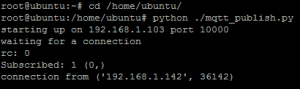
Now the installation of ROS is finished. You can run roscore on the terminal, and then ROS master will  output information like that:

linaro@linaro-alip:~$ roscore

… logging to /home/linaro/.ros/log/6fe7a434-1dea-11b2-8e0e-1000a4f31ddf/roslaunch-linaro-alip-1217.log
Checking log directory for disk usage. This may take awhile.
Press Ctrl-C to interrupt
Done checking log file disk usage. Usage is <1GB.

started roslaunch server http://linaro-alip:36980/
ros_comm version 1.11.13

SUMMARY
========

PARAMETERS
* /rosdistro: indigo
* /rosversion: 1.11.13

NODES

auto-starting new master
process[master]: started with pid [1228]
ROS_MASTER_URI=http://linaro-alip:11311/

setting /run_id to 6fe7a434-1dea-11b2-8e0e-1000a4f31ddf
process[rosout-1]: started with pid [1241]
started core service [/rosout]

That’s the installation tutorial of ROS on pcDuino8 Uno.

Viewing all 562 articles
Browse latest View live